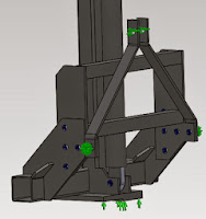
Inputting the hand calculations into FEA the following assumptions were made:
Worst case scenario. A dynamic load equivalent to a force of 35kN on the bottom plate as shown.
Model is fixed halfway along the beam to extract reaction loads.
The weight cradle is held by a hydraulic ram and allowed to slide.
2. Initial calculations show that the base of the plate yields. To remove this a 20mm by 10mm gusset is welded to the area of high stress therefore reducing it.
The diagram below shows the reduced stress to an acceptable level.
3. 10mm by 20mm reinforcement stiffeners.
4. Reaction loads were extracted from current FEA and used as load cases for the bottom section.
5. The plates were welded together, where bolted pin elements were used boundary conditions were used as shown.
6. Resultant stresses were extracted from the analysis and found to be acceptable. The diagram shows the exaggerated deformation.
7. Max stress as 64 MPa at base of welded gusset.


