Wednesday, 28 May 2014

JNDC Achieves ISO 9001:2008 For the 6th Consecutive Year

The Kingston based  engineering design consultancy JNDC Ltd has achieved the internationally recognised ISO 9001:2008 establishing it as one of the leaders in its field.

The independent assessment demonstrates the commitment to customer service and quality in delivery.

ISO 9001 was first introduced in 1987 and requires organisations to demonstrate that they do what they say they do and that they have a quality management system in place to ensure consistency and improvement; leading to high levels of performance and customer satisfaction. Certified organisations are committed to continuous improvement and are assessed annually to ensure progress is being maintained.

JNDC's Operations Director Dean Carran said, 'We are very happy to have achieved ISO 9001:2008 certification for the 6th consecutive year. This underlines our ongoing commitment to our customers and our focus on quality. This recognition demonstrates we can provide a quality solution from quotation to delivery.'


Established within the aerospace industry JNDC provide mechanical design solutions within areas such as tooling, fabrication and manufacturing techniques.  JNDC's expertise has allowed them to expand into areas such as new product development, re-life and redesign in markets such as consumer products, medical devices and industrial equipment. Using the latest 3D CAD modelling, finite element analysis, testing, prototyping and development facilities JNDC's engineers and product designers have the capability to offer a competitive price with outstanding quality and service.


Wednesday, 30 April 2014

New Employee Caught Sleeping on the Job

You really can't find the staff these days.


Zeus our new employee was so tired that sleep was the only option.

Tuesday, 8 April 2014

Manufacturing Aluminium Prototype Parts Quickly Part 3

Carrying on from my last blog, the parts had been machined and all went really well with that.

After the parts were checked, we sent them off for polishing. This took about a week to complete as it is really labour intensive, but as you can see the results are fantastic, all in the space of two weeks! What do you think?

polished aluminium partsPolished Aluminium Parts


Thursday, 3 April 2014

Manufacturing Aluminium Prototype Parts Quickly Part 2

Continuing on from my last blog in March, 'manufacturing aluminium prototype parts quickly'. The 3D printed  parts have been used as masters to make the sand casting mould and they were then sent off for heat treatment.

I printed out two master parts and gave them to the foundry, altogether we ordered 27 parts.  It's great that by only printing two parts in plastic, you can essentially use these as masters to make as many aluminium parts as needed.  We printed two because it cuts the lead time down to make the two part moulds, cutting the time almost in half.
Aluminium prototype parts

 The part up close

Aluminium prototype part


So with the parts cast and heat treated, it was now down to working out how to hold the parts to machine in the detail that was needed.  After quite a bit of discussion with the machinist, we came up with this jig that would hold the casting in place whilst milling in a deep slot on the top face.

Jig for castings

 The part post machined.
Post machined part


With all the parts machined, they are now off to polishing. To sum up that's 27 parts complete ready for surface finishing, all made from 2 3D printed masters.


Tuesday, 1 April 2014

Finite Element Analysis to re-engineer a product


JNDC were contracted to check the strength of a seat pad.
A linear static analysis was performed. Two load cases were considered as indicated in BS EN 12520:2010:
A vertical 1600N load 150mm from the centre and 100mm load from the front edge of the pad. Along with a vertical 1600N load representing a pad used in BS EN 12529:2010.


FEA linear static analysislinear static analysis


Results Case 1

Von Mises results shows a max stress of approx 68 MPa as shown in the figure below.  
When investigated further by extracting the max principal stress this was found to be 35MPa as shown below to the right. 
This is below the material limit and therefore acceptable.


linear static analysisFEA analysis


Results Case 2

Von Mises results shows a max stress of approx 41 MPa as shown in the top figure.  
When investigating this further by extracting the max principal stress this was found to be 28MPa as shown in the bottom left figure. 
This is below the material limit and therefore acceptable.

linear static analysislinear static analysis


Conclusions

- Seat pads to be re-engineered based on the rapid prototyped material.
- To redistribute stress concentrations, “fingers” of seat pad structure to be redesigned.  
- Stiffness of seat pad has increased in comparison with previous prototype manufactured.


Wednesday, 19 March 2014

Manufacturing Aluminium Prototype Parts Quickly

Once again we have the requirement to manufacture low volume aluminium prototype parts, before commissioning high pressure die casting tooling.

The part shown below needs to be manufactured within the week, it has been 3D printed in plastic. The part has been fully engineered for die casting, so drafts, shrinkage etc have already been considered.


The first step was to print out this master part 1/70th larger to take into account shrinkage from the sand casting process.

Once the sand casting is done next week, we will send off the parts to be heat treated, then onto being machined.  After machining the parts will be polished to a high mirror finish.

Fingers crossed everything goes to plan. I will update once the parts have been finished!


Monday, 10 February 2014

Increasing the Performance of a Composite Flange

Recently JNDC completed an interesting job regarding the redesign of a lamp post flange. The current flange was manufactured in steel or extremely heavy GRP and was causing problems associated with thermal mismatch as well as difficulty in assembly.

COMPOSITE FLANGE
Original Lamp Post
COMPOSITE FLANGE
Failure of original Flange


The flange, to be designed in composite, had to withstand a 50kNm moment load.

Using FEA a new lightweight flange was designed.


FEA of COMPOSITE FLANGE
FEA meshing
FEA of COMPOSITE FLANGE
FEA boundary conditions


FEA of COMPOSITE FLANGE
Finite Element Analysis


www.jndc.co.uk

Friday, 31 January 2014

Manufacturing in China, second stop Shenzhen - Part 3

Shenzhen is situated north of Hong Kong and is a major city in the south of Southern China's Guangdong Province.

Three factories were visited and the overall impression on quality and manufacturing was very good. One in particular stood out with attention to detail on the quality of tooling design and manufacture. Their approach to supporting the customer with recommendations to optimisation of the parts was extremely beneficial to improving part quality and overall costs. The photo below just shows how well the factory is laid out.  Western standards of health and safety were observed.  Simple safety devices like having light gates / laser sensors on all equipment results in extremely low injuries, all of which are minor.

Manufacturing in China
 Picture 1 - Punching and Pressing


Other factories I have seen have operators placing their hands into the machine without any safety devices.  It is hard to watch as a  250 tonne press stamps out metal seconds after a hand is removed.

As well as primarily producing component parts our chosen factory manufactures tools. Picture 2 shows a high volume of tooling that has just passed through the quality department, prior to being shipped to customer both in China and the west.

Manufacturing in China
Picture 2 - Steel Tools

Picture 3 shows factory workers hand finishing some small castings.  Again the workers have been given all the relevant PPE such as gloves, gauntlets and masks and are also working in a well lit, well ventilated area.  The company encourages inter department activities such as football and other sporting events on a weekly basis.  It was refreshing to see factory workers whose safety and well being is very much considered.

Manufacturing in China
Picture 3 - Hand finishing parts

I am sure disreputable companies exist in China as well as in the west however the trip has enabled me to see firsthand how China has the capabilities, resources and now how to manufacture successfully.

Friday, 24 January 2014

Factory Visit in Ningbo - Part 2


First stop was Ningbo, a seaport in the northeast of Zhejiang province.

The capabilities of the 1st factory include high accuracy die casting tooling and manufacturing die casting products for industries such as electrical, lighting and automotive.

product manufacture
Selection of die cast products
product manufacture
Manufacture of bbqs


This factory has an excellent record selling 80% of their manufactured tooling to both overseas and domestic markets. Their business started with die cast products only, however due to the factories high quality of tooling manufacture and capabilities this area has expanded rapidly.

large injection moulding tool
Large injection moulding tools in storage
injection moulding tool
Injection mould tool following quality check
(individual features noted as checked)
 We were very impressed with this factory, with an overall good first impression on quality of work and quality standards. Seeing the QA in action dispelled for me some of the myths regarding poor quality in China.

coordinated measuring machine
Coordinate measuring machine

Products quality system
Products going through quality checks


I noticed the poster below within the QA department. I have no idea what it says... any Chinese speakers out there?? Please let me know. Thank you!

quality manufacturing
QA Department Sign
Next stop Shenzhen.

Tuesday, 21 January 2014

China Road Trip to Source Manufacturers - Part 1

After a long flight from the UK, Dean Carran one of the directors at JNDC touched down in Beijing to start his road trip to source manufacturers for machined metal parts and aluminium castings.


Mongolia from the plane

The itinerary included four manufacturers. One in the city of Ningbo, a seaport city in the northeast of Zhejiang province. Today Ningbo is a major exporter of industrial tools, textiles, food and electrical products. The three other manufacturers were in the city of Shenzhen, a major city in the south of Southern China's Guangdong Province located immediately north of Hong Kong. Shenzhen is one of the largest manufacturing hubs in the world and the area became China's first and one of the most successful special economic zones.

The main scope of the trip was to verify capabilities and quality of manufacturing processes and outputs.

manufacturing sourcing china
Road Trip Itinerary

details of the trip to follow

Thursday, 5 December 2013

Optimizing the Design of a Pile Driver using Finite Element Analysis

Pile Driver FEA
 1. Load requirement for Hydraulic Ram = 105kN.
Inputting the hand calculations into FEA the following assumptions were made:
Worst case scenario. A dynamic load equivalent to a force of 35kN on the bottom plate as shown.
Model is fixed halfway along the beam to extract reaction loads.
The weight cradle is held by a hydraulic ram and allowed to slide.


Pile Driver FEA
2. Initial calculations show that the base of the plate yields. To remove this a 20mm by 10mm gusset is welded to the area of high stress therefore reducing it.
The diagram below shows the reduced stress to an acceptable level.


Pile Driver FEA
3. 10mm by 20mm reinforcement stiffeners.


4. Reaction loads were extracted from current FEA and used as load cases for the bottom section.


Pile Driver FEA
5. The plates were welded together, where  bolted pin elements were used boundary conditions were used as shown.


Pile DRiver FEA
6. Resultant stresses were extracted from the analysis and found to be acceptable. The diagram shows the exaggerated deformation.


Pile Driver FEA
7. Max stress as 64 MPa at base of welded gusset.


Wednesday, 4 December 2013

JNDC's New Address Details


JNDC have moved, please find below our new address details:

Unit 8, Endeavour House
2 Cambridge Road
Kingston-Upon-Thames
KT1 3JU

All telephone and internet numbers / addresses as before.

Thank you JNDC


Tuesday, 22 October 2013

Busy and Exciting Times Ahead for the Freedman Chair


The Freedman Chair is set to break records on Kickstarter.

After such a successful launch, predicted to be the most funded UK Kickstarter campaign to date, the go ahead was given to start the manufacturing process.


JNDC have been working with Simon Freedman, an osteopath and inventor, for over two years. The process has involved the engineering design, development and prototyping of the chair. The work is far from complete and the next stage, the manufacturing process, is now in full swing.


Kickstarter Updates:
http://www.kickstarter.com/projects/929020713/the-freedman-chair-a-better-way-to-sit/posts

JNDC Ltd
http://www.jndc.co.uk/

Monday, 21 October 2013

The Freedman Chair, a better way to sit - A hit on Kickstarter


Just under £100,000 pledged in the first 3 days on Kickstarter!

Kickstarter is a new way to fund creative projects. Each project is independently initiated. Project creators set a funding goal and deadline. If people like it they can pledge money to make the project happen. Projects must then reach their funding goal to go ahead.


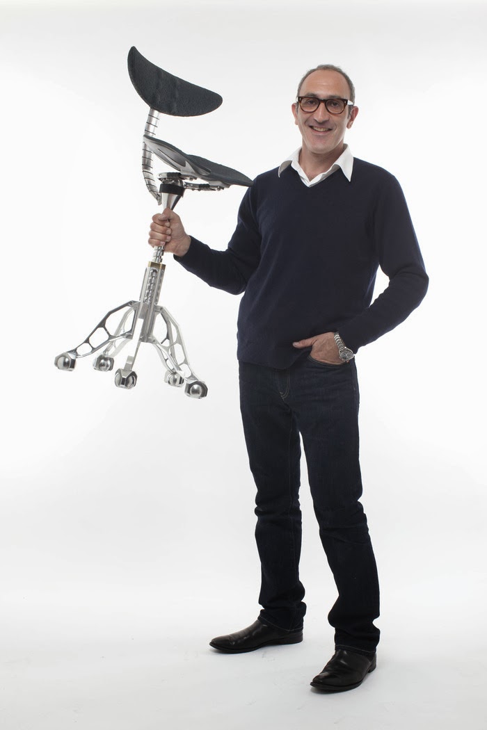
Created by osteopath and inventor Simon Freedman and engineered by JNDC Ltd; this is the only chair in the world designed to maintain your standing posture.

Simon's Story:

I'm an osteopath and inventor who set out to find a solution for my patient's problems and make a chair that was comfortable. I've been lucky enough to gather a fantastic team to help me along the way.

More and more patients were coming in to see me with aches and pains associated with sitting and I just couldn't find a chair that helped. I began to think that there must be something wrong with sitting itself, so I immersed myself in the subject. My research led me to the conclusion - we are just not meant to sit. It's a theory that's really hitting the press at the moment. I've been working on a solution for my patients of 18 years and I believe my chair will solve a lot of people's problems.

I set out to make a chair that helps the spine and pelvis achieve the same position in the sitting as when standing. I've devoted 26 years, as an osteopath, to looking after people and solving their problems. I know it probably sounds a a bit naive, but I really do want to make a difference to people's lives. I believe that The Freedman Chair will make you more comfortable, healthier and fitter than any other chair. It may even save your life.


Click the link below to see how the project is progressing :
http://www.kickstarter.com/projects/929020713/the-freedman-chair-a-better-way-to-sit?ref=category

Engineering Design Consultants:
http://www.jndc.co.uk/


Thursday, 17 October 2013

Crack Propagation Analysis

Introduction
Adhesive joints are increasingly used in various industries from aerospace to civil. They allow complex shapes to be joined and they also reduce the weight of the structure. Because of this composite materials are often bonded. Composite materials are very anisotropic, in the fibre direction they are strong and stiff however their transverse and shear properties are low. Bonded joints experience peel loading, so the most likely mode of failure is in the transverse direction either in the adhesive or the composite itself.
It is therefore important to study the joints to find reliable methodology to predict the strength of the adhesively bonded composite joints.

Method
A finite element cohesive zone model (CZM) was modelled to predict the peel strength of the joint.
The most widely used method of determining mode I interlaminar fracture toughness (peel strength) of a bonded composite joint is the double cantilever beam (DCB) test [1]. The method is based in linear-elastic fracture mechanics theory [2] and calculates GI using the crack length as well as the applied load, load point displacement crack and initial specimen width. 

Figure 1. Dis-bonding


Figure 2. The load/ displacement curves


Conclusions
The predictions of the model have been compared to the experimental data. Fig 1. shows the process of dis-bonding in the model. The load/displacement curves show a good agreement between the numerical prediction and the experimental result as shown in Fig 2.


References
1 D5528-01 (2008) Standard test method for mode I interlaminar fracture toughness of unidirectional fibre-reinforced polymer matrix composites. Annual Book of ASTM Standards 15.03.
2 Griffith A.A. (1920) The phenomena of rupture and flow in solids. Philosophical Transactions of the Royal Society of London 221(21): 163-198.

YouTube Video Link:
http://youtu.be/9wDuB6ZkRBs


www.jndc.co.uk


Friday, 4 October 2013

Pre-production Prototype Case Study - The chair that could save you life

Background
JNDC previously designed and manufactured two series of prototype seats to undertake extensive research and development in relation to ergonomics.  Following the completion of the second round of prototyping the customer instructed JNDC to undertake design for manufacture as well as the manufacture of 5 "pre production" prototypes.


Development
Moving from a detailed prototype to a final pre-production prototype required JNDC to revisit every part to optimise for manufacture.  Weight, cost, manufacturability as well as the overall look and feel of the chair had to be considered.  In addition, advanced prototyping techniques had to be selected to mimic a final manufactured part, without going to the expense of investing in expensive tooling.
Sand casting, silicone moulding as well as CNC milling and turning were the key processes used to develop the 5 pre-production prototypes.  JNDC coordinated the manufacture of all parts, and when complete undertook the complete assembly process in house to ensure the quality of the final product met and exceeded the customer's expectations.


Next Steps
The prototypes are now being used for marketing, from trade shows to photo and video shoots through to pitching to potential distributors and buyers.  The preproduction prototypes will also be used to receive accurate quotes from manufacturers, allowing the companies to see the physical items that they will be manufacturing in high volume.