Wednesday, 25 September 2013

Component Finite Element Analysis Work - L Bracket Assembly


Continuing on from the last blog this project invloved FEA analysis to be carried out on a L bracket assembly used to hold a roof window. The customer specified a total load of 700N acting on the assembly at the rotation point, causing a moment load to the main attachment lugs one of which is attached to the window the other to the roof frame.

CAD L Bracket Assembly


 The study results showed that the maximum Von Mises stress in the bolted region were well within acceptable levels. The maximum Von Mises stress occured away from the lug that were beyond yield of the material at the interface of the fold.

To reduce the high stress at the fold interface the model was changed by moving the fold 10mm and introducing a stress reducing hole of 5mm. Reducing the stress yeild value.


Tuesday, 24 September 2013

Component Finite Element Analysis Work - Sheave Assembly


We have been busy working on numerous projects over the last couple of months.

Finite element analysis work on components seems to be very popular, we will be blogging a few small examples:

Sheave Assembly
JNDC were contracted to perform an FEA analysis on the sheave assemblies to establish yield stress under a static load of 14,400lbs. (64,054N)

CAD  SHEAVE ASSEMBLY

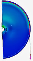
The analysis was carried out in two stages, the first was a quarter model testing the wheel with bearings and the second part was the aluminium structure.

Fine mesh was used to control the areas of high interst as shown:
The study results showed high stresses at the interface of the cable and wheel. Also the high stress showed the interface of the bearing with the fixtures as expected.
FEA Sheave AssemblyFEA SHEAVE ASSEMBLY


Monday, 23 September 2013

Threaded Inserts in Rapid Prototype Parts / Could this be a Solidworks add on ....


We make a lot of plastic prototypes here for our customers.  Whenever we  need a tapped hole we just print the part with the correct diameter hole and then physically tap the plastic part after it is printed.  I use the Solidworks hole wizard to make sure I call up the correct sized hole for tapping after.  This has worked for us really well in the past, however recently we have found that the threads do wear over time. So I decided to get some threaded insert samples sent to me to try them out in the next prototype we make.  
We usually need threads from about M3 to M6 in size, so I got a range sent to me to do some investigation work on.


I have a few plans.  Firstly, work out how well these inserts work and also to see if I can work out how to modify hole wizard in Solidworks to have a function for easily making the correct sized hole for these threaded inserts.  I am not sure if it will be within the hole wizard option, a separate add on, or even a tool box item.  I am keen to work it out as we would use it a lot here at work if the inserts work out well for us.


Is there anyone out there who cam help with this one ?? Or if you have any experience using the inserts, do let me know.  Many thanks!!!


engineering design thread inserts

Friday, 20 September 2013

From Solidworks CAD concept to Aluminium in a day....all down to 3D printing and Solidworks!

The Journey to Find Cost Efficient Aluminium Rapid Parts Continued - Part Six


So I got into the office early this morning, to find an urgent job that needed an aluminium part!

We did the CAD quickly, sent it to our Uprint 3D printer and I have just arrived back from the foundry with 5 castings!  To some it might not sound like much, but for us, managing to go from concept to aluminium parts in less than 12 hours is fantastic.

Here is a screen shot of the part in Solidworks.
CAD Solidworks


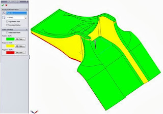
So after doing the initial CAD I used the Solidworks tools to check the draft angles to make sure the foundry would be OK casting the part without having to rework any of the plastic master.

Here is a screen shot mid way through checking.


CAD Solidworks


Using the scaling tool, I added 3% to its size and then saved it as an STL ready for the printer. 

The UPrint 3D printer took 2 hours to print the part, and I jumped in the car and dropped it off at the foundry.

Mid afternoon I got a call to say they were ready for collection.

For those of you out there use to working with castings, it will look quite good.  Those of you not so used to seeing a raw casting it looks very rough around the edges.  Because it was such a quick job the foundry have not trimmed off the flashing (thin parts of aluminium that seeps into the split line of the sand mould).

So I will be spending the rest of Friday afternoon filing back the flashing. First thing Monday morning the parts can be heat treated so they can be a fully structural part.

Its quite an exciting process, and its great to know it can be done...

raw aluminium parts

raw aluminium parts


Rapid prototyping to aluminium cast parts in 3 days... Solidworks add on Idea!

The Journey to Find Cost Efficient Aluminium Rapid Parts Continued - Part Five


It has been quite some time since the last time I put up the blog.  This is mainly down to us being really busy utilising this new process. 

At the end of my last blog, I just received back the first cast parts having used rapid prototyped master parts in the sand casting process.  I finished off by saying that I needed to check the parts physical dimensions and compare them to the CAD.  Unfortunately we don't have any laser scanning / CMM here at our facility, but using calibrated callipers (easily accurate to .05of a mm) I set about measuring the part.
Overall I was very pleased with the results.  The part came back with a very good tolerance.  Based on a rage of measurements made between 60mm to  100mm, they all came back being slightly larger by an average of 0.5mm. I must be clear that this is clearly not an accurate representation of the accuracy of the overall part, however as an initial indication we were very impressed. 

Also, I had to remind myself that the design of a cast part falls into two areas, highly tolerance areas, and lower tolerance areas.  In the past when designing aluminium cast parts I found one of the important elements of the design is to ensure datum's are provided for our machinists to have a good reference point to work from.

Since the last blog, we have probably made about 12 to 15 different aluminium parts, all of which have been successfully used in the design and manufacture of prototypes and low volume products. 


cast partsengineered cast parts


These two parts came back really well, and as you can see have very little flaws in the cosmetic appearance.  You can see the split line in the left hand part, but that can't really be avoided given the geometry.

This next photo shows how we post machined the areas that needed to have a high level of tolerance.

Cast Parts


So now that we have done this process with quite a few parts, I am finding that it really gives us a competitive advantage over a lot of other companies that use more traditional manufacturing processes for low volume aluminium parts.  Now we know which days of the week the foundry pour aluminium, we can have the parts from CAD to being back in our workshop within 2 days, but 3 days is a little more relaxed for the foundry.

A good example of how useful this can be is during the product development process.  We can now have parts in aluminium much earlier on in the design process, allowing our customers to have a much better idea of how their product looks and feels as well as physically performs.

My next plan for this project is to see if I can find anyone out there who can help me with developing an add on to Solidworks so we can develop a design checker, specifically for the rapid prototyping / sand casting process.  I was thinking of having quite a few inputs such as rapid prototyper accuracy, type of aluminium used, even down to inputting data from previous cast parts to the add on can accurately predict the shrinkage. 

Now clearly this is a lot of work, but it would be great to develop a free add on for anyone to use. Please di get in touch if you can help in any way, or indeed would like this add on once it is developed! 


The Chair that Could Save Your Life - Huge Hit at 100% Design

100% Design Earls Court
Simon Freedman an osteopath and inventor was seeing more and more people whose problems are caused by prolonged sitting, or by the lack of a suitable chair. He has been creating a seat that allows the spine and pelvis to achieve that same posture in sitting when standing.

Exhibiting at the 100% Design Show in Earls Court has caused  huge interest for this unique chair. The next steps being the launch on kickstarter on the 27th of September.


Working with Simon for over 2 years JNDC has been using computer aided design (CAD) software to assist in the prototype development process. The design has seen several key areas change over the project, to simplify the parts and promote the best seating position.

engineering design


From CAD structural analysis was undertaken to check the seat flexed and behaved in the desired way. Prototyping has been involved and intense, utilising methods such as CNC machining right the way through to sand casting and silicon moulding.

Dean Carran Operation Director at JNDC said: 'It is a pleasure working with Simon to develop his ideas, the project is going from strength to strength and I can see the chair as a must for environments where prolonged sitting occurs'. 

The latest prototype has had lots of fantastic feedback, JNDC are looking forward to working on the next exciting stage of the project.

For more information visit : www.freedmanchair.com  /  www.jndc.co.uk