The Journey to Find Cost Efficient Aluminium Rapid Parts Continued.
Following on from the last blog, 3D Printing for Sand Casting, I am going to cover what I
plan to change in CAD to make sure the plastic master part will work when it is sent to the foundry for sand casting. We use Solidworks here at work, but all the functions I will
be talking through can be found in other CAD software too.
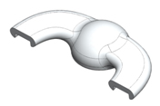
Below is the part that I need to have cast in Aluminium ( Image 1):
 |
| IMAGE 1 |
 |
| IMAGE 1 |
As you can see its quite a simple part, with some hollow
features on the underside.
The areas below need to be checked:
- Prue Location
- Riser Location
- Flow & Gas Escape
- Draft
- Shrinkage & Hot Spots
- Final Draft Check
- Scaling
Sprue Location:
A sprue is essentially the passage in the mould where liquid
metal is introduced into the mould. The
foundry use years of skill to design the physical shape of the sprue as there
are many considerations (that I am will cover in more detail in another blog)
but for this first test I need to consider where the liquid aluminium will flow
into the mould. Once it has flowed into
the mould, the excess metal in the sprue will solidify and will require cutting
off the final aluminium part.
 |
| IMAGE 2 |
I have chosen the flat face highlighted in green for the place
where the aluminium will enter the mould, Image 2. It will also be easy to remove the excess metal from the sprue as the
surface is flat (as opposed to one of the curved surfaces).
Riser Location:
When the molten aluminium flows through the part, it needs
another volume to flow into to make sure the aluminium has completely filled
the mould. (As with the detailed design
of the Sprue, I will cover the design of the riser in another blog). Exactly the same principle of removing the
sprue applies in selecting a good location to remove the riser. The face highlighted in red is ideal, as its
the same easy geometry to make a flat cut through.
Flow and Gas Escape:
This part is very simple, there are no areas where
gas can collect and prevent the liquid aluminium from flowing into. There is no need to consider
adding other vents / risers into the design of the part.
Draft:
Draft is essentially the amount of taper on the part to help
during the mould making process.
The part at the moment has parallel walls (highlighted in
blue, Image 3). When the plastic part is removed
from the sand during the mould making process, there is a risk that the
parallel walls could drag against the sand, causing it to distort /collapse.
 |
| IMAGE 3 |
I have added draft to the walls, making them 3 degrees off parallel. Image 4. Having this small amount of taper really
helps the plastic part being removed from the sand with minimal risk of the
sand being distorted.
 |
| IMAGE 4 |
Shrinkage:
If there is a large volume of aluminium next to
thin features in a part, the aluminium will cool unevenly. The small thin features will cool first,
while the large volumes of aluminium will cool much slower. As you can see I have taken a few section
views to check that the thickness throughout the part is similar, avoiding the
risk of uneven shrinkage, Image 5.
 |
| IMAGE 5 |
 |
| IMAGE 5 |
The section views show that there are not any large volumes
of aluminium that will cool unevenly. If
there are large volumes that cannot be avoided, chills can be put into the sand
mould that draw the heat out of the hot spots, giving a more evening cooling
rate, reducing the risk of the part being highly stressed /deformed from
uneven cooling.
Final Checks:
The CAD we typically use here in the office is Solidworks and
it has a great "Draft Analysis" tool to double check that I have not
forgotten to draft any faces.
 |
| IMAGE 6 |
All the faces "looking upwards"
are in green, meaning that every face has at least 3 degrees of draft, Image 6. The two end faces are highlighted in yellow,
showing that draft is in theory required, however, these faces are the ones
where the sprue and riser are connected to the part.
Just as an example, I have removed the 3 degrees of draft on
the vertical walls and you can see that the analysis tool has flagged up in
yellow all areas of the feature that need draft, Image 7.
 |
| IMAGE 7 |
Scaling:
Now I have double checked the part, the only thing to do is to scale the part up. After doing a lot of
reading around, I believe that 3% increase gives good results.
I have now saved the part, converted it to the format that
our 3D printer here at work can read, and I will print the part over night and
drop it off at the foundry next time I am over.
I will keep you posted on progress!
·


